Vista TF is a quasi-2D solver designed to give a quick response to design input for turbomachinery applications. This tutorial gives a brief introduction to the Vista TF component along with Vista CPD, BladeGen and BladeEditor.
Introduction
The TF in Vista TF is an abbreviation for “Through Flow”. Vista TF is a two dimensional solver designed to give a quick response to design input for turbomachinery applications. The solver solves quasi-2D on a “S2-surface” and enables designers to quickly improve basic design parameters in an early stage of the design cycle.

The solver treats the fluid as being inviscid. To make up for the loss in accuracy resulting from this simplification, Vista TF applies empirical models. The equations are circumferentially (pitchwise) averaged.
This tutorial will show how to quickly investigate the flow field in a centrifugal pump by using Vista TF.
The geometry used in Vista TF could be imported to Design Modeler (DM) from an external file if you would like to get a quick response from changes in your own design. In this tutorial we will use Vista CPD (Centrifugal Pump Design) to generate the blades of the pump.
The Vista CPD is included along with the other Vista tools from release 14.5. If you have an older version, you need to import BladeGen to the Workbench project and open the Vista CPD from there.
Drag the Vista CPD component into the Workbench Schematic.

Double click on Blade Design. A window like the one below will be showed.

Input variables are used to give a basic starting point for the pump design. The head, volume flow, rotational speed and other parameters could be changed to the specific purpose.
Leave the parameters as default as shown in the figure above and click “Calculate”. Notice the result tab and the efficiency chart which becomes available.
Close the Vista CPD and select the it in the Project Schematics. On the right hand side of the workbench window you will see the Properties of Schematic window. Change the Impeller export type to “Coupled to Volute” instead of “Isolated Impeller”.

Right click on the Blade Design component, and select Create New and BladeGen. This tutorial will demonstrate the entire workflow from input values in Vista CPD to final results by Vista Throughflow. This way, manipulation of the geometry in BladeGen or BladeEditor will be possible. If Throughflow is chosen instead, all the next steps will be automatically generated and results produced.


Various windows show the design parameters, like the angle and thickness distribution. These parameters could be changed by drag-and-drop in the respective windows.
The complete geometry could be visualized by clicking on the box in the menu panel on the right hand side.

Save and close Blade Gen and import a geometry component to the Workbench project. Do not connect the Geometry and BladeGen components. Before starting DM, it’s important to do one adjustment in the license hierarchy in order to get the Blade Editor toolbar within Design Modeler.
In Ansys Workbench, click “Tools” > “License Preferences”

Go to the “Geomery” tab in the window that occurs and select ANSYS BladeModeler and click “Move up” in order to have the ANSYS BladeModeler license on top, as showed in the figure below.

Start DM. Notice the Blade Editor Toolbar that is added to the regular toolbars in DM.
ANSYS BladeEditor is a plugin for ANSYS DesignModeler for creating, importing, and editing blade geometry.
It is important to notice the difference between Load BGD and Import BGD. If you convert a BladeGen BGD file into BladeEditor features (that is, load a BGD file) by clicking “Load BGD”, then you can modify the blade by editing any of the features in the Tree Outline. By contrast, if you instead import a BladeGen file, the flow path and blade shape cannot be edited in BladeEditor. The import can however be refreshed if there are any changes to the BladeGen file. Since we want to perhaps edit the blade shape and construct a flow path in BladeEditor, we will use the “Load BGD” tool to import the geometry in this tutorial.
Click Load BGD on the Blade Editor Toolbar. Navigate out of the user_files folder, and into dp0 > BG > TS folder where the geometry from BladeGen is saved as default by Ansys Workbench. A MerPlane, FlowPath and Blade are added to the Tree Outline. Click on Blade1 and change the Blade Extension (%) to 5. Generate to complete the loading of the design.


The different parameters could be set as design parameters or changed to preferred value. The geometry could be changed by “Drag-and-Drop” in the curves on the right side of the screen.
Click “VistaTFExport”, select “Blade1” and press “Generate”. The geometry will now be prepared for the Vista TF solver.
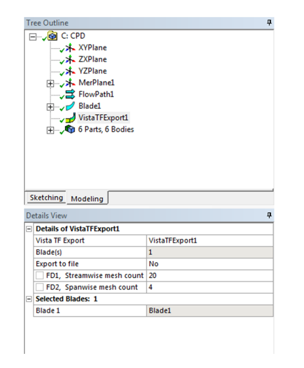
Leave streamwise and spanwise mesh count as default in this tutorial.

In Ansys Workbench, drag-and-drop the Vista TF component onto the geometry. By clicking on “Setup”, the pump’s operation criteria’s could be specified.
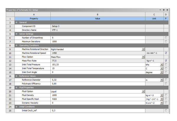
Design points for a parametric study can be spesified in the setup, and within seconds or minutes, the solver will produce tendencies and responses to parametric input. These results could of course be compared with results obatined by a three-dimensional CFD solver such as Ansys CFX or Ansys Fluent.

Comparing Vista TF results and CFD results
Source : EDR MEDESO